Comprehensive and Strategic Analysis of Installation, Engineering, and Quality Management Processes of Geomembrane Liners in Hydraulic and Environmental Structures
In recent decades, the geosynthetics industry has become the backbone of waste management, water resource protection, and industrial infrastructure development. Within this domain, geomembranes, as polymeric membranes with exceptionally low permeability, play a vital role in physically segregating contaminants from the ecosystem and preventing the loss of valuable resources. However, the efficiency of these complex systems is not solely limited to the quality of the raw materials; rather, the ultimate continuity and durability of a lining system strictly depend on the precision of installation operations, subgrade engineering, and quality control protocols during execution. Neglecting installation standards not only leads to physical failure of the layer but can also trigger catastrophic, irreversible environmental disasters, the remediation costs of which will be several times the initial cost of a standard installation.
Materials Science Fundamentals and Polymer Selection Criteria in the Design Phase
Prior to commencing any execution operations, a detailed analysis of the mechanical and chemical properties of various polymers is essential to match the specific requirements of the project. The selection among High-Density Polyethylene (HDPE), Linear Low-Density Polyethylene (LLDPE), and Polyvinyl Chloride (PVC) is a function of environmental variables, expected physical stresses, and the type of fluid in contact with the liner.
Technical Anatomy of Polyethylene and PVC Geomembranes
Due to their semi-crystalline structure, HDPE geomembranes offer the highest level of chemical resistance against acids, bases, and hydrocarbons, making them the premier choice for landfill liners and chemical storage containment. On the other hand, LLDPE, by offering higher flexibility and superior environmental stress crack resistance (ESCR), is preferred for projects subjected to potential differential settlement or those requiring floating covers. PVC, owing to its high weldability and compatibility with irregular geometries, has found widespread application in tunneling projects and irrigation canals.
It is crucial to understand that additives such as carbon black (typically 2% to 3% by weight) and antioxidant packages (primary and secondary antioxidants) are added to the formulation not merely for coloration, but to protect the polymer chains from degradation caused by ultraviolet (UV) radiation and thermal oxidative processes during installation and operation.
Logistics, Manufacturing Quality Control (MQC), and Pre-installation Management
The installation process practically begins at the manufacturing plant. Each geomembrane roll must be produced under strict MQC protocols and possess a valid technical passport, which includes the roll number, date of manufacture, and physical property test results. Any visual defects, such as air bubbles, physical impurities, or deep scratches on the sheet surface, must be identified at the source, and defective rolls must be marked.
Transportation and Site Storage Standards
Handling heavy geomembrane rolls requires specialized mechanical equipment, such as forklifts equipped with stinger bars or cranes with spreader bars, to prevent damage to the central core of the roll and the edges of the sheet. The site storage area must be a flat, dry, and well-drained surface; placing rolls on rocky or uneven ground, which causes the sheets to deform under their own weight, must be strictly avoided.
Subgrade Engineering and Preparation of Underlying Layers (Subgrade Preparation)
As the physical foundation and support for the geomembrane, the installation subgrade is the primary determinant of the lining system's mechanical lifespan. Any unevenness in the subgrade can lead to the "bridging" phenomenon, wherein the sheet is overstretched under fluid pressure, ultimately resulting in tearing.
Technical Requirements for Leveling and Compaction
The ground surface must be cleared of all debris, tree roots, sharp stones, and metallic pieces. Rounded, edgeless stones with a diameter of less than 50 mm are permitted to remain in the subgrade only if they are driven into the soil via rolling and leveled with the subgrade surface. Subgrade compaction must reach at least 95% of the maximum dry density according to the ASTM D698 standard to prevent localized settlement, which exerts severe shear stresses on the sheet.
In cases where the subgrade soil contains coarse or abrasive particles, installing a protective geotextile layer with an appropriate mass per unit area (cushion) between the subgrade and the geomembrane is mandatory. This layer not only prevents punctures but also acts as a gas venting layer, preventing the accumulation of underground gases that lead to the formation of "whales" or large bubbles beneath the sheet.
Design and Execution of Anchor Systems (Anchor Trench Design)
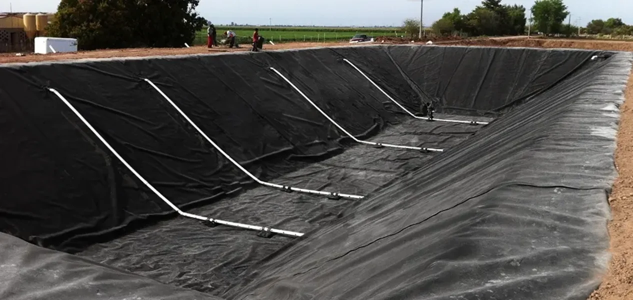
The edges of the geomembrane panels along the project perimeter must be placed inside anchor trenches to resist tensile forces resulting from slope sliding and wind uplift forces.
Anchor Trench Design Parameters
Anchor trench design is an engineering balance between acting forces and resistive forces derived from the weight of the backfill soil and the friction between the sheet and the subgrade. The standard dimensions for most medium-sized projects are 12 inches in width and 24 inches in depth; however, in projects with steep slopes or thick sheets, these dimensions must be modified based on stability calculations.
The backfilling process of the anchor trench must be carried out during the coolest hours of the day so that the sheet is anchored in its state of maximum contraction. This strategy ensures that during the hot hours of the day, the sheet retains sufficient freedom of movement for expansion without undergoing destructive tension.
Panel Deployment and Strategic Layout Operations
The deployment of sheets must be executed according to a pre-approved panel layout diagram, which specifies the position of each panel and the serial numbers of the rolls. The primary objective in this phase is to minimize the number of seams and, specifically, to eliminate cross-seams in high-pressure areas such as reservoir floors and mid-slopes.
Management of Environmental Variables During Execution
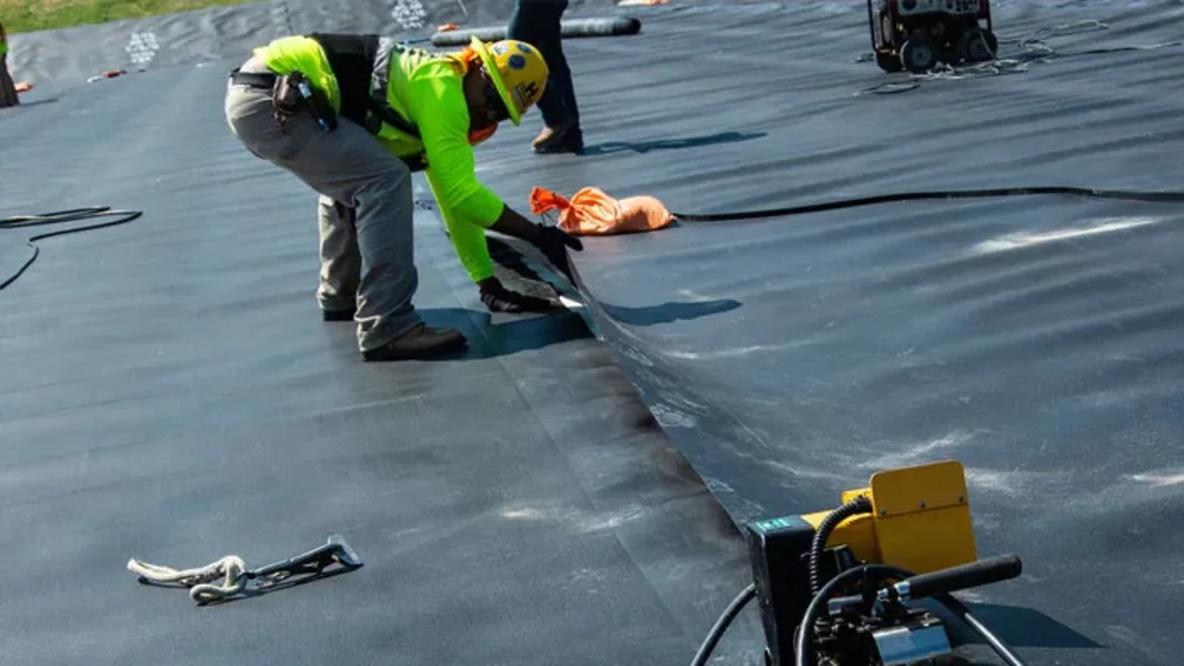
Geomembrane installation is heavily influenced by atmospheric conditions. At low temperatures, the sheet becomes rigid, making it difficult to conform to corners, while at high temperatures, the potential for mechanical damage to the sheet due to personnel and equipment traffic increases. The direction of panel deployment must always align with the prevailing wind direction to prevent air from penetrating beneath the layers. The use of sandbags weighing 50 to 75 pounds as temporary ballast to anchor the panels until final welding is completed is mandatory.
Advanced Technologies in Polymeric Seaming and Welding
The beating heart of any geomembrane project is the quality of its seams. A lining system is only as impermeable as its weakest seam. Two primary methodologies exist for creating a molecular bond between panels: thermal fusion welding and extrusion welding.
Dual Hot Wedge Welding Mechanism
Considered the "golden technique" in the industry, this method utilizes a self-propelled machine equipped with a hot metal wedge that moves between two overlapped layers, heating the surfaces to their melting point. Immediately following heating, squeeze rollers compress the two molten layers together, causing the polymer chains to mix at the molecular level. The use of a split wedge is a mandatory standard in critical projects because it creates a central air channel for subsequent pressure testing.
Extrusion Welding and its Specialized Applications
Extrusion welding is a process in which a molten polymer welding rod is extruded onto the joint edge via a hand-held extruder. This method is primarily used for patching, repairing holes, and intricate detailing such as pipe boots and reservoir corners. Prior to the extrusion operation, the sheet edges must be abraded using a specialized grinding tool to remove the surface oxidized layer and form a stronger bond, provided that the grind depth does not exceed 10% of the total sheet thickness.
Optimization of Welding Operational Parameters
Achieving a quality "Film Tear Bond" (FTB) weld requires precise calibration of three key variables: temperature, speed, and pressure. A crucial technical point is that during cold-weather welding (below zero degrees Celsius), the machine speed must be reduced by 20% to 30% to allow sufficient time to reach the melting temperature.
Quality Control (CQC) and Quality Assurance (CQA) Systems
The testing and inspection process must proceed concurrently with installation so that any defects can be identified and rectified at an early stage.
Non-Destructive Testing Protocols
- Air Channel Test: Performed on dual-track seams, this test is the most efficient method for verifying the continuity of long seams. Both ends of the channel are sealed, and air is injected at a pressure of 25 to 30 psi. If the pressure drop is less than 3 psi after 5 minutes, the seam is approved.
- Vacuum Box Test: This method is used to inspect patches and extrusion seams. By applying a soapy solution and creating a vacuum inside a transparent box, the appearance of any soap bubbles indicates a leak in the seam.
- Spark Testing: In this method, a thin conductive wire is inserted inside the seam during welding. By passing a high-voltage neon gun over the seam, any discontinuity or puncture triggers a spark between the device and the wire, pinpointing the exact location of the leak.
Destructive Testing Analysis
Destructive tests are performed to ensure the mechanical strength of the seams. Typically, a sample is cut every 150 meters (500 feet) of seam for shear and peel testing. In the peel test, the seam must not separate at the joint interface; instead, the failure must occur within the geomembrane sheet itself (FTB), indicating a complete molecular bond.
Operational Challenges: Wrinkles, Wind, and Critical Weather Conditions
Geomembrane installation is not a static process and is constantly in conflict with environmental variables. Managing these variables marks the difference between a professional installation and a failed project.
Wrinkling and Bridging Phenomenon
Polyethylene geomembranes exhibit a high coefficient of thermal expansion. During the day, solar radiation causes the sheet to elongate, creating large waves or wrinkles across the surface. If these wrinkles are not managed during backfilling or impoundment, they remain as permanent distortions and, under load pressure, become highly susceptible to stress cracking. The solution to mitigate this issue is utilizing a "progressive installation" approach and executing the final backfilling during the cool hours of the night or early morning when the sheet is not in its most expanded state.
Strategies Against Wind Uplift
High winds can lift wide geomembrane panels like an airplane wing, causing displacement or even complete tearing. To manage this challenge in large-scale projects, calculations for the threshold wind velocity are conducted. If necessary, permanent concrete weights or heavy protective layers (riprap) are utilized to permanently anchor the sheet against wind forces.
Human Resources and Qualifications of the Execution Team
Installation quality is directly correlated with the experience and expertise of the personnel. International standards, such as those from the IAGI (International Association of Geosynthetic Installers), have defined specific criteria for the qualification of installers.
Key Roles in the Installation Team
- Field Installation Supervisor: Holds overall responsibility for panel layout, welding, and testing, and must possess a verified record of installing at least 5 million square feet of geomembrane.
- Master Seamer: The individual who directly oversees the welding process and must have at least 3 million square feet of seaming experience with similar equipment.
- QC Technician: Responsible for conducting pressure and vacuum tests and accurately documenting the data in daily logbooks.
Life Cycle Management: Inspection, Maintenance, and Post-Installation Repairs
A geomembrane project does not conclude with the completion of installation; rather, it enters a critical operational phase that requires continuous monitoring.
Periodic Inspection Protocols
Visual inspections should be conducted quarterly and immediately following natural events such as hailstorms, high winds, or earthquakes. Inspectors must look for signs such as discoloration (UV degradation), surface cracks, settlement at the edges of the anchor trench, and any leakage around rigid connections. If a puncture caused by external factors (such as bird pecking or falling objects) is observed, immediate repair using standard patches and extrusion welding is mandatory to prevent water from penetrating beneath the liner and undermining the subgrade.
Advanced Electrical Leak Location (ELL) Solutions
In recent years, the use of Electrical Leak Location (ELL) systems as a complement to conventional testing has become widespread. In this method, by utilizing the electrical potential difference between both sides of the membrane, even microscopic holes that cannot be identified by eye or vacuum testing are located with millimeter precision. This technology is particularly applicable to containment reservoirs for toxic materials and nuclear waste, where zero leakage is vital.
Final Analysis and Strategic Recommendations for Impermeable Projects
The execution of a geomembrane lining system is a synthesis of materials engineering, thermal physics, and rigorous project management. Success in this field requires shifting from the traditional perspective of "laying sheets" toward a holistic view of "engineering protective containment systems." Material selection must be performed considering the half-life of antioxidants under project temperature conditions to prevent premature oxidative degradation. Subgrade preparation goes beyond simple leveling and must include geotechnical stability analyses to prevent settlement-induced failures.
In the execution phase, relying on welding technologies with closed-loop control systems to automatically regulate temperature and speed minimizes the risk of human error. Furthermore, precise documentation of every panel, every seam, and every test in the form of digital as-built drawings will serve as the foundation for maintenance management in the coming decades. Ultimately, a commitment to complying with standards such as ASTM and GRI at all stages—from resin production to the tenth year of operational inspection—is the only way to guarantee the protection of soil and water resources for future generations. This comprehensive report demonstrates that the cost of quality in the early stages is a smart investment to prevent the exorbitant costs of system failure in the future.